

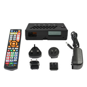
Bitfunx OSSC HW V1.8 Open Source Scan Converter HDMI™ Adapter for PS2 SEGA Saturn Nintendo64 Gamecube MD Retro Game Consoles
For Product Technical Support:1. Please join the Bitfunx Discord :https://discord.gg/ewRspdnt3Z2. Please visit Bitfunx Official Store to contact customer service. 3. E-mail :Bfse@sofunretro.com4. Visit Bitfunx on Youtube to see more videos of the product in use.(https://www.youtube.com/@Sofunretro)Bitfunx OSSC HW V1.8 Open Source Scan Converter HDMI™ Adapter for PS2 SEGA Saturn Nintendo64 Gamecube MD Retro Game ConsolesIntroductionThe Open Source Scan Converter is a low-latency video digitizer and scan converter designed primarily for connecting retro video game consoles and home computers to modern displays. It converts analog RGB or component video signals into a digital format, and doubles (or triples) the scanlines of a single frame if necessary to generate a valid mode for digital TVs or monitors.NOTE: Before purchasing the product, please confirm whether your game console can output the input signals supported by OSSC.OSSC supports input signal: RGB(Scart), VGA, Component. Use the operation video link:https://www.youtube.com/watch?v=PtpqUIuby98https://www.youtube.com/watch?v=skHlJOoagVgNew Features of V1.8 OSSC:1. Improved Hardware Compatibility:Version 1.8 includes revisions to the hardware to improve compatibility, especially in terms of sync/mode detection.2. Shadow Mask CRT Simulation:This feature emulates the shadow mask effect found behind traditional CRT screens, offering users a more authentic retro gaming experience.3. HDR Mode:The addition of HDR (High Dynamic Range) mode provides a wider color range and contrast, making the images look more vivid and lifelike.4. 1440p Pixel Repetition Mode:This feature allows the OSSC to enhance image quality when outputting at 1440p resolution by repeating pixels, which is useful for users who want better image quality on high-resolution displays.5.Improved Power/Ground Supply Distribution:With a new 4-layer PCB design, version 1.8 improves the distribution of power and ground, contributing to overall performance and stability.6. Inherited Features from Version 1.7:This includes over-voltage protection, an improved audio switching switch, and reduced temperature and power consumption. These improvements have been carried over to version 1.8.OSSC OVERVIEWLED's Status Green LED indicates that power is on. This green LED will go out briefly when an lR remote code is detected.The red LED indicates unstable sync when lit.LCDDisplays the 0SSC's menus and information about the current source.MicroSD Card SlotFor updating the devices firmware.IR SensorReceives commands from the remotecontrol unit. Line of sight is required.JTAG ConnectorFor software development purposes and firmware updates.BTNO and BTN1Perform various functions without the need of a remote control.Video outOn V1.5 and earlier models, an industry standard DVl-Dconnector outputs digital video at chosen resolution to your display. Does not support/output analogue DVl. On V1.6 andlater revision units only OSSC models this is replaced by a standard HDMI™ connector.Audio out (V1.5 and earlier revisions only)Standard 3.5mm stereo headphone plug type connector.Audio fed in through AV1 (RGB SCART) will be output here.If an audio upgrade board is installed, you can also feed in analogue audio through this connection, but please notethe SCART cable should be disconnected from AV1 first.AV2 audio in/AV1 audio out(V1.6 and later revision units only)Standard 3.5mm stereo headphone plug type connector.Use this connector to output audio from AV1/SCARTor to input audio for AV2/Component video sources.Audio toggle (V1.6 and later revision unitsonly) Toggle between outputting audio from AV1or inputting and digitizing audio on AV2.AV3 audio in (V1.6 and later revision units only)Standard 3.5mm stereo headphone plug type connector.Use this connector to input and digitize audio for AV3/D-Sub15 (VGA) sources.AV1 In Connect an RGB SCART source to this input.Important:The input must be an RGB or YPbPr signal. S-Video and Composite SCART sources are NOT supported and require transcoding into RGB first, Only European specification RGB SCART cables are supported. The less common Japanese JP21 cable must be used with a converter.AV2 InConnect component video or RGB with sync on green sources to this input.AV3 InStandard D-Sub15 (VGA) connector. You can connect sources such as the Sega Dreamcast or a retro gaming PC.This input does NOT have a sync low pass filter as this isnormally not required for VGA connections. Signals up to amaximum resolution of 720p are supported on all inputs.Power SwitchToggles the power off and on.Power inputConnect a suitable 5 volt, 2.1 x 5.5mm positivetip PSU supplying at least 1 amp of current.OSSC Remote If your remote control is unresponsive: Operation Video: https://youtu.be/iL3MQPaiDSE1) Power cycle the OSSC while holding BTN1 on the OSSC's PCB.2) A target function name (e.g. "MENU") will then be displayed on the OSCC's LCD screen. Press the corresponding key on the remote control (the key you want to use for the displayed function). If the OSSC receives the code correctly you will be prompted to confirm the new code. Press the same key again to confirm.3) Continue to do #3 for every function that displays on the screen. Assign a unique button to each function.Firmware UpdateNew features are periodically added to the OSSC in the form of firmware updates. The devices firmware can be updated using an MicroSD card. The MicroSD card should first be formatted with the new firmware. Once this is done, insert the card into the OSSC, enter the menu and choose “FW. update”.The firmware files are named usingthe following conventions:-jp-Japanese language version-aud- Digital audio enabled version suitable for 0SSC-aud -jp-As above with Japanese language translationFAQ: Q1: Why my remote control not responding?A1: Please go to YOUTUBE and search @GameBitfunx to view the operation video.Q2: How to update the Firware of OSSC?A2: Please go to YOUTUBE and search @GameBitfunx to view the operation video.Q3: What signal inputs and outputs does OSSC support?A3: Input Signal: Scart (RGB) / Component / VGA. Output Signal: HDMI™Q4: How to use OSSC?A4: Please go to YOUTUBE and search @GameBitfunx to view the operation video.

Prime Supply_Play Life
Review

You May Also Like

Ulanzi R099 Clamp Mount with Mini Ball Head (2993)
WUBUWEI | Elevating Desktop Organizer Dual-layer White Storage Rack
LG Magic Remote Control AN-MR18BA - Google Voice & Mouse Pointer - For LG Smart TV

Universal Travel Adapter Socket Extension Multi-Country Plug Converter with 2 USB Ports for Home Office Hotel Kitchen Appliances

7RYMS Qshot V2 Magnetic Phone Selfie Monitor Screen Support 4K 60fps Wired Recording Using Phone Rear Camera for Selfie Vlog LiveStream Compatible with Android iPhone HarmonyOS
(SG STOCK) Wireless Mouse Rgb Led 2.4Ghz Silent Rechargeable 1600dpi Slim Portable With USB Receiver Computer PC Laptop
Sanrio | Cute Hello Kitty Phone Case Large Camera Window Soft Shockproof Protective Cover For iPhone 13 14 15 Pro 16 17 Pro Max For Girl

Divi | Anti-Drop Rotating Stand Case
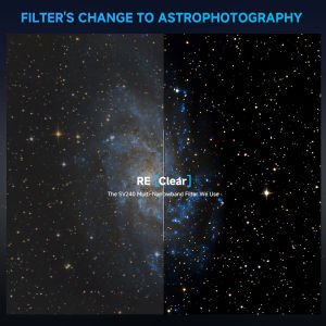
SVBONY SV240 Multi-Narrowband Filter Galaxy & Nebula NIR Near-infrared Light Pollution 2" Mounted for Urban Astrophotography
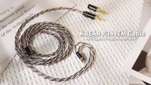
Kbear | KBEAR HiFi 5N2-Strand 98-Core Oxygen-Free Copper Headphone Upgrade Kit - Replaceable Plug Design for Audiophiles And Musicians

USB Rechargeable Intelligent Leafless Hanging Neck Fan Portable Mini