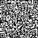


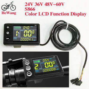
24V 36V 48V-60V S866 Color LCD Display for Protocol 2 Electric Bike Scooters 5PIN+2PIN (2pin for Light)
Note: Error code E06 occurs, the product defaults to 36V, this is an undervoltage situation, you can manually adjust the meter to adapt to 24V, or check the battery and adjust it to 24V and wait for about 10 seconds. Do not touch anything during this period. It will convert automatically. Video link: https://video.aliexpress-media.com/seller/play/5000264806825.mp4Note: If error code E07 occurs, the power assist PAS cable (red, yellow, black) and the throttle cable (red, green, black) are connected incorrectly. Follow the wiring video link, or rewire the throttle cable and adjust the throttle cable (red, green, black) signal line. Reference videos: https://video.aliexpress-media.com/seller/play/5000298772350.mp4 and https://video.aliexpress-media.com/seller/play/5000298772350.mp4Note: If error code E10 occurs, it indicates a loose connection at the instrument panel connector. Try unplugging and replugging the cable. Refer to the video website: https://video.aliexpress-media.com/seller/play/5000376402889.mp4Model LCD-S866Wire Specifications: 5-pin + 2-pinVoltage: 24V-48V-60Features: LED-lit cableProduct Name: LCD Color ScreenColor: BlackConnector: SM StandardOperating Temperature: -20°C-60°CCompatible with Type II protocol controllers LCD Display 866User Manual V.20221. Exterior ParametersCasing Material: ABSDisplay Material: High Hardness Acrylic (the same hardness value as tempered glass). Front View Side View2. Operating Voltage and Connectionsa. Operating Voltage: DC24V / 36V / 48V (set by the display menu). Otheroperating voltage can be customized.b. Connectors:Standard Connector TypeController Connector Display Output Connector Coupling Input Connector Standard Connector Arrangement Sequence No. Wire Colour Functions1 Red(VCC) Display Power Cable2 Blue(K) Controller Power On/Off Cable3 Black(GND) Display Ground Cable4 Green(RX) Display Data Receiving Wire5 Yellow(TX) Display Data Sending WireExtended FunctionsLight: Brown (DD): The positive electrode of the light White (GND): The negative electrode of the light.The wire color definitions of the PWM Voltage Motor Power Controller and theindependent speed sensor will be defined otherwise.*Note: Some products use waterproof connectors, whose internal wirearrangements cannot be identified from the exterior.3. Functionsa. DisplaySpeed Display PAS Level Display Battery Level DisplayError Indication Total Mileage Single MileageLight Indication Single Trip Timeb. Control and SettingsPower Switch Front Light Control 6km/h Cruise ControlReal-time Cruise Control Wheel Diameter Setting Top Speed SettingSleep Interval Setting Backlight Brightness Setting Voltage Level Settingc. Communications Protocol: UARTDisplay Interface(Displayed for 1sec at start)Display Interface3.1 Light3.2 Battery·3.3 Speed Display Measuring Unit: MPH or KM/HThe display will calculate the actual travelling speed based on the wheeldiameter and signal data (number of magnetic steel is needed for Hall motors).3.4 Multi-Function DisplayTotal Mileage: ODOSingle Mileage: TRIPError Code: ERRORPower: WATTStart Time: TIBattery Voltage: VOL3.5 PAS Level 3.6 Cruise Indicator 3.7 Error Code and IndicationsError Code(decimal)Indications Note0 Normal1 Reserved2 Brake3 PAS Sensor Failure (riding mark) Not Realized4 6km/h Cruise5 Real-Time Cruise6 Low Battery7 Motor Failure8 Throttle Failure9 Controller Failure10 Communications Receiving Failure11 Communications Sending Failure12 BMS Communications Failure13 Light Failure3.8 SettingsP01: Backlight Brightness (1: darkest; 3: brightest)P02: Mileage Unit (0: KM; 1: MILE)P03: Voltage Class 24V / 36V / 48VP04: Sleep Interval(0: never, other value means display sleep interval) Unit: minuteP05: Power Assist Gear0/3 Gear Mode: Gear 1: 2V Gear 2: 3V Gear 3: 4V1/5 Gear Mode: Gear 1: 2V Gear 2: 2.5V Gear 3: 4V Gear 4: 3.5V Gear 5:4VP06: Wheel Diameter Unit: inch Precision: 0.1P07: Magnet Steel Number (for Speed Test) Range: 1-100P08: Speed LimitRange: 0-50km/h, parameter 50 indicates no speed limit.1. Non-communications status (panel-controlled)When the current speed exceeds the speed limit, the PWM output will be shutdown; when the current speed falls to lower than the speed limit, the PWMoutput will be activated and the driving speed will be set as the current speed ±1km/h (only applies to assist power speed, not applicable to the handlebarspeed).2. Communications status (controller-controlled) The driving speed will be kept constant as the limited value. Error Value: ±1km/h (applicable to both the assist power/handlebar speed) Note: The above-mentioned values are measured by metric unit (kilometers).When the measuring unit is switched to imperial unit (mile), the speed value displayed on the panel will be automatically switched to corresponding imperialunit, however the speed limit value in the imperial unit interface won’t changeaccordingly.P09: Direct Start / Kick-to-Start Setting 0: Direct Start 1: Kick-to-StartP10: Drive Mode Setting 0: Power Assist – The specific gear of the assist drive decides the assistpower value. In this status the handlebar does not work. 1: Electric Drive – The vehicle is driven by the handlebar. In this status thepower gear does not work.2: Power Assist + Electric Drive – Electric drive does not work in zero-startstatus.P11: Power Assist Sensitivity Range: 1-24P12: Power Assist Starting Intensity Range: 0-5P13: Power Magnet Steel Number 5 / 8 / 12pcsP14: Current Limit Value: 12A by default; Range: 1-20AP15: UnspecifiedP16: ODO Zero-OutLong press the up key for 5 seconds and ODO value will be erased.Note: Due to product upgrade, the product you purchased may beslightly different from the descriptions in this user manual, and thiswon’t affect normal usage.

GlobalSuperBazaar
Review

You May Also Like

EUSSUE | Insulated Large Outdoor Camping Tent Pyramidal Design
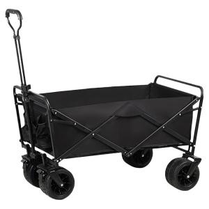
JIBUZHE | Collapsible High Capacity Lightweight Camping Trolley
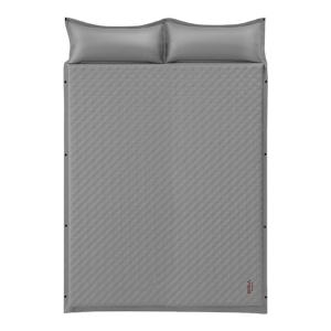
The Primitive | Automatic Inflating Camping Mattress

TOSUOD | Night Riding Light Strong Beam Flashlight Mountain Bike Headlight Waterproof Rear Light Cycling Equipment
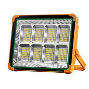
Solar Rechargeable Super Bright Portable Spotlight
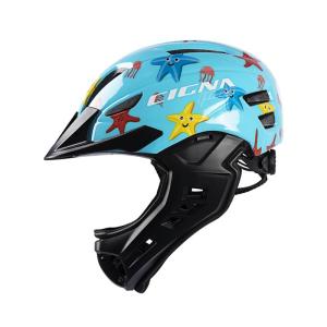
CIGNA | Child Safety Helmet for Balance Bike and Bicycle

GUOQI | Arch Support Training Device Toe Exercise Foot Adjuster
Helang | Silent Omnidirectional Ab Roller Wheel
ANCHUN | Thickening Rubber Ramp Mat
5PCS DIY Lure Making Components Kit for 15cm Baits – Includes Popper Skirts Jig Heads Squid Skirts
5-Compartment Fishing Lure Box – Clear Plastic Tackle Organizer for Hooks Frogs & Soft Baits