

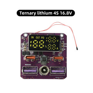
diymore | LED Battery Charging Protect Board 4S PD 100W Bidirectional Fast Charging Discharging Module Type-C+USB+DC Port
Features1. 100W bidirectional fast charging to meet high-speed charging and discharging needs2. Powerful 20V/5A output, suitable for applications such as power banks and energy storage systems3. Intelligently identifies device requirements to safely and efficiently match charging current and voltage4. Effortlessly handles device charging, significantly reducing charging wait times5. Automatically adapts to multiple protocols including fast charging and standard charging, offering broad compatibility with mainstream electronic devicesParameterType-C1 Input: 5V-3A, 9V-3A, 12V-3A, 15V-3AType-C2 Input: 5V-3A, 9V-3A, 12V-3A, 15V-3A, 20V-3.25AType-C1 Output: 5V-3A, 9V-3A, 12V-3A, 15V-3A, 20V-5AType-C2 Output: 5V-3A, 9V-3A, 12V-3A, 15V-3A, 20V-3.25AUSB A1 Output: 5V-3A, 9V-2A, 12V-1.5A (22.5W), 20V-5A (UFCS protocol)USB A2 Output: 5V-3A, 9V-2A, 12V-1.5A (22.5W), 20V-5A (UFCS protocol)DC Port: DC 55×21 mm with real-time display of battery level, voltage, and currentImportant Notes1. Do not solder while the device is powered on. When soldering the + and - wires to the main board, ensure the protection board has no output voltage to prevent 99.99% of accidents.2. The main board has only + and - terminals. Soldering while powered on can easily cause damage if your hand shakes. Please disconnect the power before soldering. Connect the main board’s + and - terminals first. Solder the battery pack’s negative terminal last—solder the battery pack’s negative terminal last!!! The two wires on the main board cannot balance the battery; the balancing protection function is on the lithium battery protection board.Frequently Asked Questions1. Protection board wiring for a 4S battery pack: Start from the negative terminal. The first positive terminal (b1) is 4.2V. Subsequent terminals are b2 (8.4V), b3 (12.6V), and b+ (positive terminal, 16.8V). Connect the protection board’s P+ and P- terminals to the main board’s + terminal.2. If the battery has power but the device does not light up or function after connection, please charge and activate it via the C port first. Regardless of whether the battery has power or how much charge it holds, it must be charged and activated.3. After charging and activation, the display may show 0 or 100. The battery level may not be accurately displayed upon first power-up; it will return to normal after a few charge-discharge cycles.4. During use, if charging stops at 80% or discharging cuts off at 20%, this is caused by inconsistent voltages. In the worst-case scenario, if the battery voltage drops below 3V while the full charge voltage is 4.2V, the battery becomes unusable.Upgrade Features1. The main controller has been upgraded to SW6306V, and the USB-A female connector has been upgraded to a 5-pin version.2. Software update: The screen now displays battery voltage. Customers using this as a startup power supply no longer need to add an external voltmeter.3. Added a DC 5.5/2.1mm port. This port connects directly to the main board’s + and – terminals; there is no conversion or voltage regulation. The output voltage matches the battery voltage exactly. It can be used to charge the battery at 16.8V or for output, with a current limit of 10A.Package includeModule *1

Prime Supply_Play Life
Review

You May Also Like
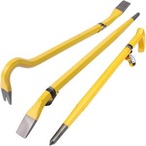
STANLEY | Heavy Duty Solid Steel Crowbar Pry Bar
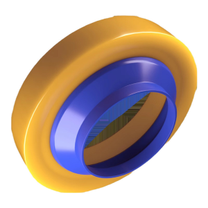
JIAYUN | Odor-Preventing Thickened Extended Toilet Wax Ring
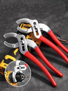
Wide Opening Hand Drill Chuck Pliers Soft Jaw Multi Functional Anti Slip Adjustable Drill ChuckValvesBathroomsPipe Pliers
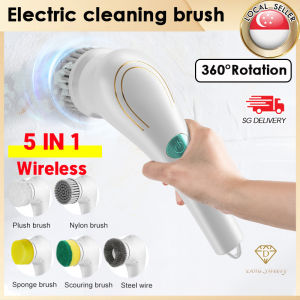
🇸🇬【SG stock】5 in1 Electric Cleaning Brush Brush Electric Cordless Cleaning for Tub and One Touch Operation & 5 Replaceable Brush Heads For Kitchen Bathroom Toilet Washbasin
![[LOCAL] Luxury Modern Square Kitchen Sink Stainless Steel Nano Black Sink With Stretch Faucet & Waterfall Free ShippingFast shipping](https://img.lazcdn.com/g/p/5b340b39e9e60cd219c763782c658c79.jpg_300x300q80.jpg)
[LOCAL] Luxury Modern Square Kitchen Sink Stainless Steel Nano Black Sink With Stretch Faucet & Waterfall Free ShippingFast shipping

JIGHOLE | T Slot Miter Track Stop Block Alloy Limiter Woodworking Table Saw Sliding Bracket Miter Gauge Fence Connector Stopper

JUE-FISH 90g White Shoe Cleaner Yellow Shoe Stain Remover Multi Function White Shoes Cleaning Gel To Remove Yellow Edges Stains White Shoes Cleaning Gel Clean Shoes Stain Whitening Shoe Cleaning Cream Polish Gel For Sneaker Shoes Remove Yellow Edge
Hansgrohe | Stainless Steel Pull Down Faucet and Sink Set
![🔥 [SG Seller]🔥 3D PVC Wallpaper - MANY COLORS!](https://img.lazcdn.com/g/ff/kf/Sd571db4e2fba4ac590a0fb225de558cbj.jpg_300x300q80.jpg)
🔥 [SG Seller]🔥 3D PVC Wallpaper - MANY COLORS!
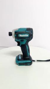
Makita | Makita DTD172 18V LXT Cordless Brushless Impact Driver 180 N·M T-Mode Electric Drill for Wood And Bolt Driving
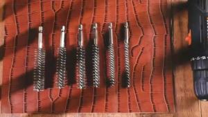
6/12Pcs Stainless Steel Wire BrushDrilling Cleaning Brush Set 1/4 Inch Hexagonal Handle Grinding Polishing Rust Removal Tools