

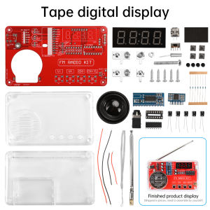
Aideepen | DIY FM Radio Electronic Kit 50-108MHz Adjustable IC RDA5807 with LED Digital Display DIY Soldering Kit 3W Speaker Dual Power
Features:1. Constructed with premium materials, featuring a transparent plastic casing and double-sided epoxy circuit board for simple operation and easy soldering.2. Equipped with a radio module offering noise cancellation, bass enhancement, high sensitivity, low noise, and strong anti-interference capabilities.3. Button-operated controls for channel switching, volume adjustment, clearing all channels, and rescan/preset storage.4. Multiple configurations available: Basic version without digital display, version with digital display, or version with digital display and charging module—select according to needs.5. Wide applicability: Suitable for school teaching, hobby cultivation, scientific research, DIY enthusiasts, etc.Product Specifications:Material: Transparent plastic casing, double-sided epoxy circuit boardName: FM Radio Construction KitControl Chip: RDA5807 8002D (STC81K17 for digital display version)Power Supply: 3 AA batteries or 3.7V lithium battery (not included)Speaker: 1.5-inch 4Ω 3W speaker (40mm outer diameter)Frequency Range: 50-108 MHzSignal-to-Noise Ratio: >60dBSensitivity: Frequency Response: 150Hz-20KHzProduct Dimensions: 1157028mmDifferences:1. Digital Display Version - Bare Components with Housing: Shipped as a set of bare components with housing. Displays radio frequency. Requires 3 AA batteries (not included) for power.2. Basic Version - Bare Components with Housing: One set of loose parts with housing shipped. Does not display radio frequency. Requires 3 AAA batteries (not included).3. Digital Display Version Loose Parts - Housing with Charging Module: One set of loose parts with housing shipped. Includes charging module, charging cable, and lanyard. Can be fitted with a lithium battery. Displays radio frequency. Requires lithium battery or 3 AAA batteries (not included).Instructions for Use1. Power Source: Slide switch up for battery power; slide down for MICRO USB power.2. After powering on, the indicator light illuminates and a static sound is heard. Then extend the antenna to tune stations. [If the indicator light is on but no sound is heard, disconnect power, wait about 30 seconds, then reconnect power.]3. Channel Selection: Press CH+ to select the next channel; press CH- to select the previous channel. [Channel selection simultaneously scans stations; patience is required]4. Volume Adjustment: Press V- to decrease volume, press V+ to increase volume.5. Headphone Usage: Insert headphones into the headphone jack for audio output. [Headphones not included in kit]6. Extend the antenna during station search and operation. Adjust its direction for optimal reception. In areas with dense buildings or remote mountainous regions, fewer stations may be available or none may be found.Soldering Method:1. Solder wire requirements: Diameter 0.8-1mm, melting point around 183°C. Do not use high-melting-point solder.2. Soldering iron requirements: 30-40W3. Maintain soldering tip cleanliness: A layer of black oxide on the tip forms an insulating layer, reducing heating efficiency.4. Soldering procedure as shown below: Most joints require approximately 2-3 seconds to complete.Strictly adhere to soldering requirements:1. Verify component quantity and model numbers. Test measurable components with a multimeter where possible.2. Follow installation steps in the tutorial.3. Install low-profile components before taller ones.4. Solder components in sections as each part is installed, trimming excess leads promptly.5. During soldering, ensure the temperature is not too high and the duration is not too long, as this may damage the circuit board or components.6. After soldering, recheck solder joints for quality and verify correct component placement.7. During power-on testing, ensure the power supply polarity is correct. Voltage must not exceed 3V.8. When securing the enclosure with screws, tighten them firmly but avoid over-tightening.9. If malfunctions occur, first verify the power supply is correct, then inspect component placement and solder joints.Radio Tutorial: http://www.diyleyuan.com/JC/2690.htmlProduct List:1X Radio Kit (DIY components shipped separately; customer soldering required.)

Prime Supply_Play Life
Review

You May Also Like
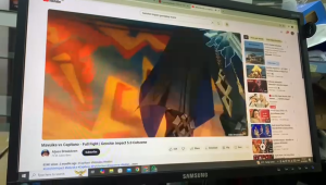
Samsung Monitor 22" S22E450F | 1920x1080 Full HDMI | Adjustable stand for Height | VGA DVI and HDMI Refurbished | Refurbished as New
LANLIPU | Gaming 4K 280Hz 2K Rotatable Low Blue Light Display 27 Inch
diymore | Mini ESP32-S3-N16R8 Development Board For Xiaozhi Ai Voice Dialogue Robot Module With 0.96-Inch Oled Screen Type C

ASUS NUC 14 Pro Tall Mini PC Barebone Kit Intel Core Ultra 7 Intel Arc Graphics DDR5 5600 WiFi 6E(3Yrs ASUS Warranty)
Seagate | Cinema-Grade Hard Drive 1TB
ASUS | Processor Motherboard Kit
BenQ EX271UZ 27" 4K 240Hz OLED 0.03ms GTG VESA HDR400 MOBIUZ Gaming Monitor
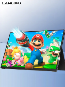
LANLIPU | External Gaming Portable Monitor IPS Touchscreen
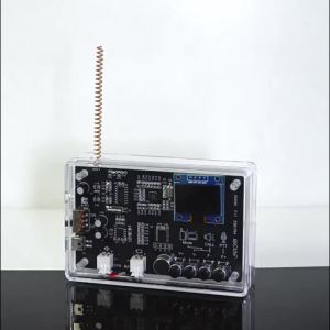
diymore | Interphone Radio Wireless Intercom FM Radio Circuit Board Production Soldering Electronic DIY Kit Practice Loose Parts Micro USB

Aideepen | Flash Strobe Controller Flasher Module for LED Brake Light Tail Stop Light 12-24V SK-CD0102 SK-CD0101 SK-CD0100
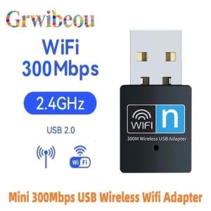
NEW Mini 300Mbps USB Wireless Wifi Adapter WiFi Network LAN Card 802.11n RTL8188 Adaptor Network Card for PC Desktop Computer